Nixie Tube Characterization
Published:
This post is Part 1 in a three part series on our design of a USB powered Nixie Tube Clock display.
Part 2 discusses the design of the power supply that steps up 5V to 170V.
Part 3 describes the design of a circuit which controls the display using isolated control signals.
Nixie Tube. What is that?
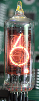
Nixie tubes are Cold Cathode display tubes that light up when a high voltage is applied across them. The source of the illumination is electronic excitation and de-excitation. This mechanism is similar to the one used by more modern Neon Display tubes.
Present day display technology, right from 7 segment displays to LCD screens work by making multiple independent sources light up in a synchronized manner. A Nixie tube is different in that it has the shapes of all digits 0-9 present as separate cathodes. The digit(s) corresponding to the grounded cathode lights up with a beautiful yellow color. For this reason, a typical Nixie tube has at least 12 pins. 10 Cathodes each for the digits 0-9, one cathode for a decimal point and 1 Anode.
For more information on Nixie Tubes and their working see this link.
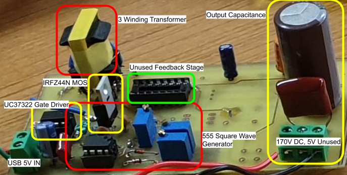
Nixie Tubes were a leading digit display technology during the 1970s - 80s. Nowadays, these displays are admired and valued for their Retro (Classic) look. Nixie Tube clocks have been a popular hobby project for many years now. Most of these projects use rectified AC mains as their power source. They do so since, the tubes have a somewhat high operating voltage of (about) 170V DC. What makes our project unique is that it succeeds in powering up the Nixie Clock Display using only a single 5V USB power supply. To know more about how our power supply does this, see part 2 of this series.
The limitation of using USB as our power source lead to another challenge; the power available through the host Single Board Computers USB port is not enough to light up numerous Nixie Tube units simultaneously. Multiplexing is a solution commonly employed in displays to save on power. It works by rapidly turning display units on and off in sequence making sure that only a single one glows at a time. Multiplexing takes advantage of the persistence of human vision to make it seem like all displays are turned on at the same time.
To check if the power budget problem could be overcome it was necessary to understand the I-V characteristics of the Nixie tubes. We had at our disposal, some now off-market, Nixie Tubes by Bharat Electronics Limited (BEL) which were loaned to us by our advisor Mukul Chandorkar.
I- V characteristics
In the absence of available documentation on our BEL tubes, we performed our own characterization experiments which are described here. The I-V characteristics of the tubes were quite necessary for the design of our power supply.
This is the case since the feasibility of powering the clock from a computers USB port must first be assessed. Moreover details like the peak current drawn are essential for the design of the transformer in the isolated power supply.
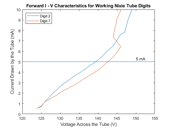
The I-V characteristics for the digits 2 and 7 are shown to the right. Some observations here are-
- The current requirement at a particular operating voltage point varies slightly from digit to digit
- This was expected due to physicial difference between the shapes of the two cathodes
- The characteristics of the Nixie Tube are somewhat similar to that of a diode
- Current picks up rapidly as voltage is increased and soon current starts to increase rapidly for small increases in voltage
- This also highlights the importance of the presence of a series resistance while operating these tubes since there is no significant internal resistance
This characterization was done using a full bridge rectifier, an autotransformer connected to AC mains and a small circuit board with a filter capacitance, a capacitor discharge pathway (for when power is turned off, indicator LED also present) and a series resistance. Readers familiar with electronics would recognize this as the standard AC-DC conversion circuit. Two multimeters were used to act as voltmeter and ammeter.
Power Budgeting
The voltage level available from USB is 5V as is well known. The maximum current that a single USB port can be expected to provide is 500mA. This caps the available power at approximately 2.5W. As seen in the previous section, a single tube draws about 10mA of current at 150V glowing very brightly, thus requiring 1.5W approximately. Hence as it can be seen, the there isn’t much margin for inefficiency in the design of the power supply, but designing one is certainly feasible.
Experiments with a Faulty Tube
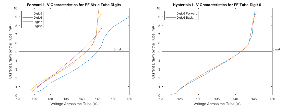
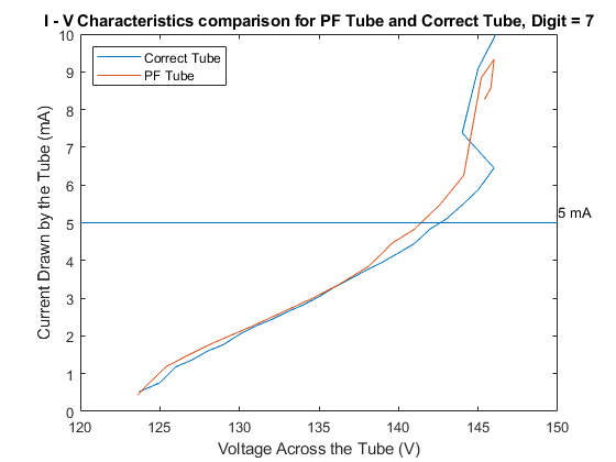
In an initial experiment we blew out the 0 digit of a Nixie Tube due to our faulty method of recording its I-V characteristics. We didn’t include with the tube a current limiting series resistor. This caused a current overload through the 0 digit cathode rendering it useless. This tube is referred to as partially faulty (PF).
We thought it would be an interesting exercise to observe if a problem with one cathode affected the I-V characteristics of any other digit. Based on comparisons with the data from the correct tube mentioned above, and the plot on the right comparing I-V characteristics for digit 6, we can conclude that damage to one digit’s cathode does not affect the performance of other digits.
Hysterisis
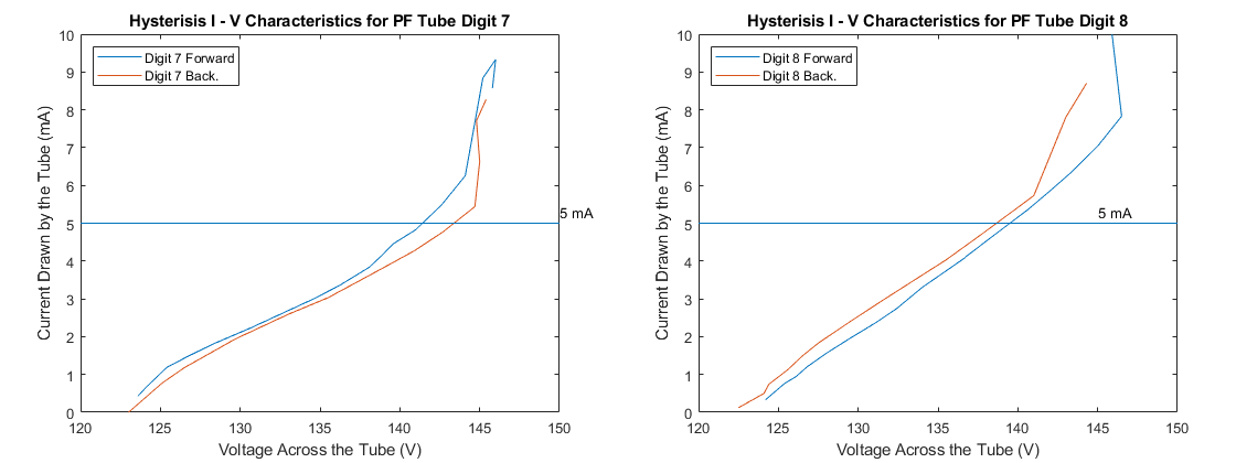
In addition to the forward I-V characteristics (Increasing voltage) we also performed retreating I-V characteristics. The retreating characteristics involved decreasing the voltage down from the highest V reading to the turn off voltage. We were inclined to document this behaviour since the tubes were seen showing Hysteresis.
This means that the current requirement for a particular digit can be different depending on whether we are moving forward from the turn on voltage or decreasing the voltage applied. That being said, the current difference is quite low, in the (μA) range.
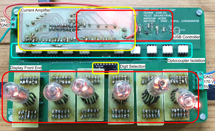
Precious Tubes need Holders
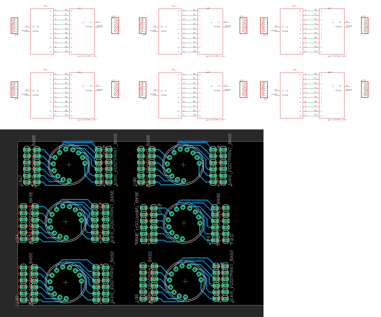
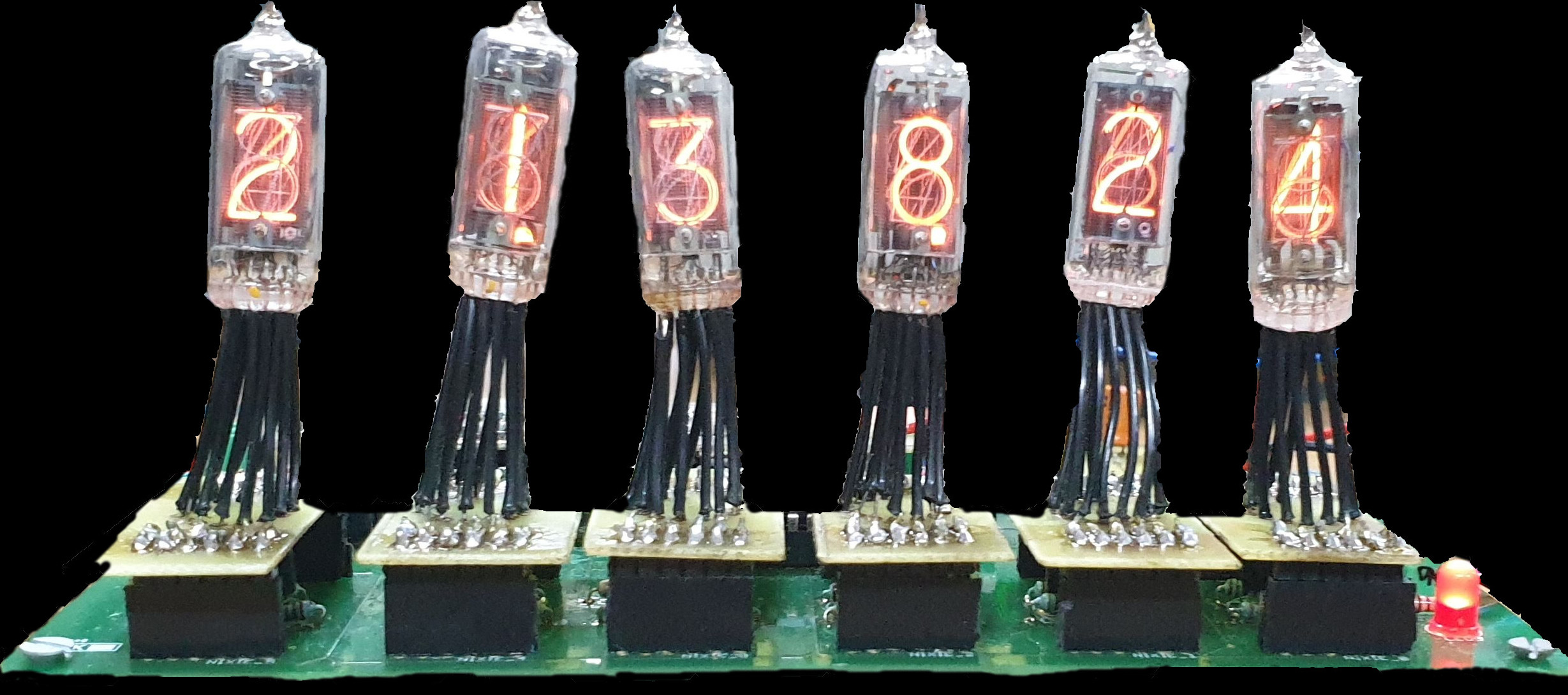
Nixie Tubes are something of a novelty. So to keep the option of using these tubes in another project open, we wanted to make them socketable. On failing to find a viable off the shelf solution we decided to design our own tube holders as small PCBs with pin heads plugging onto the main controller board. The design is pictured above and the real life finished product is pictured below.
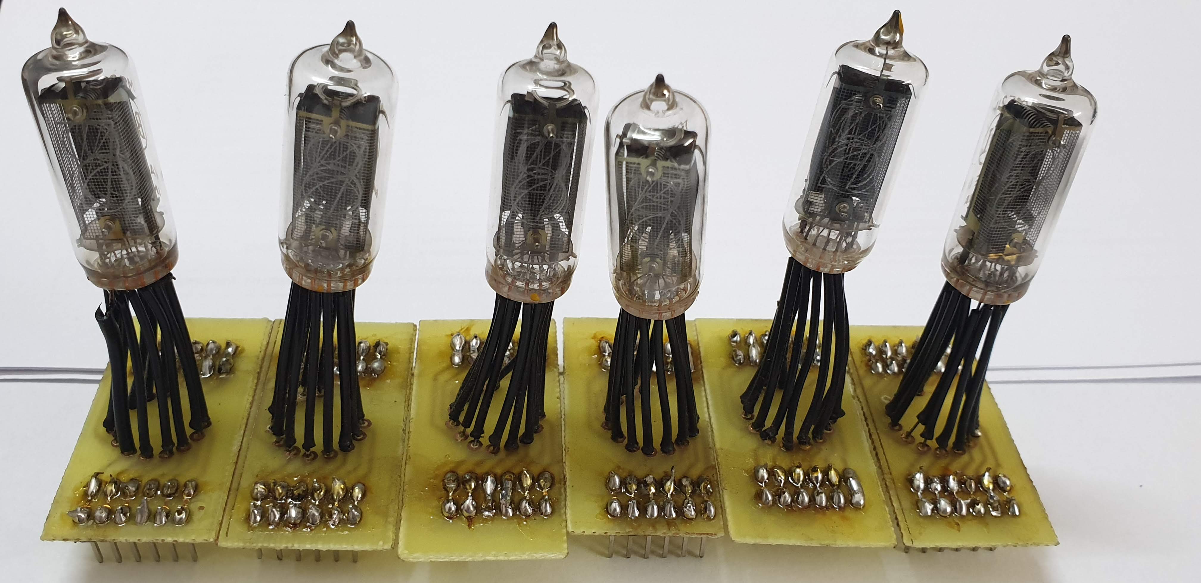
Some of the tubes are noticeably bent and crooked on these holders. The reason for this was that the legs of the tubes were quite fragile and even a small amount of strain to the leg-glass joint could potentially break the terminal off. So, after breaking a leg on one of our spare tubes, we didn’t try bending the legs of any of the tubes.
This project was completed in partial fulfilment of the requirements for EE 344: Electronic Design Lab at IITB
A more detailed description of the project along with schematics can be found in our project report
A demonstration of our project can be found here